
How to make NC program for STL file in CAMWorks
The rising popularity of 3D Scanner comes along with a significant increase of demand for processing STL files on CNC. We often hear the question “What to do with a STL file from a 3D Scanner?”, hence, we decided to create this blog to take these 3d scan data files and make them useful for you!
In this blog, we’ll show you how to make NC program for a STL file in CAMWorks.
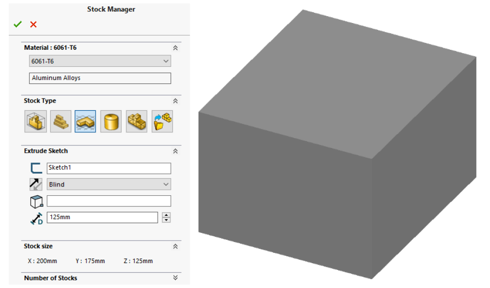
Simlar to normal file programing, we need to define Machine, Stock, and Coordinate System. When we define the stock over here, we use Stock type: Extruded Sketch as Bounding Box Stock Type can’t be used on STL files.
1. Define machine
- Use the following parameters:
Machine: Mill – Metric
Tool Crib: Tool Crib 2 (Metric)
Post Processor: M3AXIS-TUTORIAL
2. Define Stock
The following parameters should be used to define the stock size in the Stock Manager:
- Material: 6061-T6
- Stock Type: Extruded Sketch
- Select Sketch for the sketch to extrude
- Set the end condition to Blind
- Set the extrude depth to 125mm
- The stock size should be X:200mm Y:175mm Z:125mm
3. Define Coordinate System
- Define the coordinate system to use the top center stock position as shown.
- Make sure the Z direction is correct.
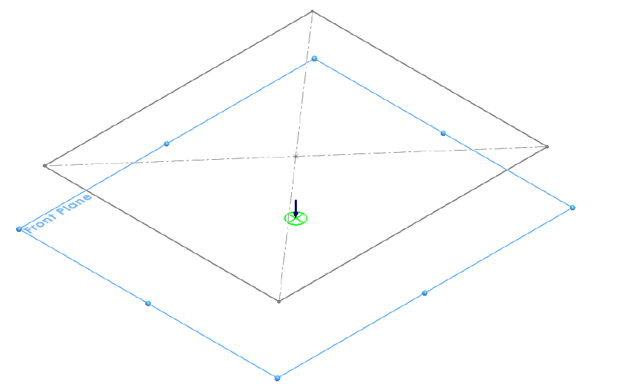
4. Create a Mill Part Setup
- Create a Mill Part Setup using the Front SOLIDWORKS reference plane
- Make sure the arrow is pointing in the direction shown
- Click OK
5. Create new Multi Surface feature
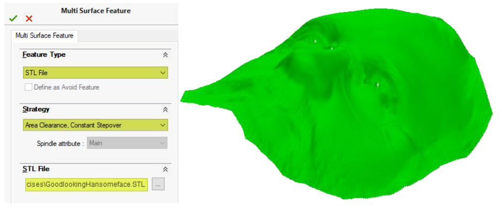
- Create new Multi Surface Feature
- For the Feature Type Method, select STL File
- Browse to the file GoodlookingHandsomeFace.STL in the \Lesson_02\Exercises folder
- Click OK to the file open dialogue
- For Strategy, select Area Clearance, Constant Stepover
- Click OK
6. Generate Operation Plan
7. Set the Automatic Contain Area
-
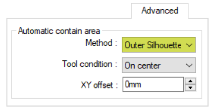
- Edit Area Clearance1 and go to the Advanced Tab
- Under Automatic contain area, set the Method to Outer Silhouette
- Edit Constant Stepover1
- Go to the Advanced tab
- Under Automatic contain area, set the Method to Outer Silhouette
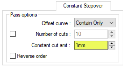
- Go to the Constant Stepover tab
- Under Pass options, set the Constant cut amt: to 1mm
8. Generate Toolpath
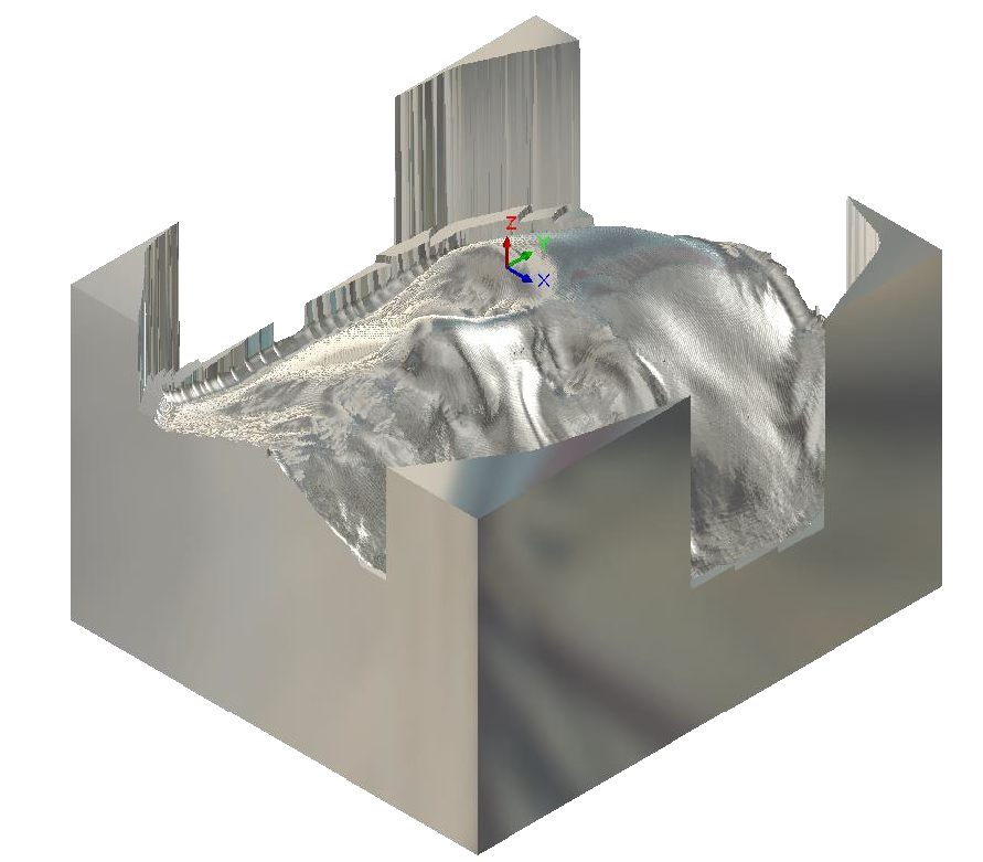
9. Simulate Toolpath
If you find this blog useful, please feel free to spread the word!
For all Technical Support related queries please send an email to support@seacadtech.com or contact us at +65 6226 3784
To know more about our products, email us at marketing@seacadtech.com or contact us at +65 6372 1416
Learn more about our training programmes and courses here


