No products in the cart.
How to Scale an Assembly in SOLIDWORKS: A Practical Guide for Engineers
April 10

April 10
When working with complex designs in SOLIDWORKS, engineers often encounter the need to resize an entire assembly—whether for concept validation, prototyping, or adapting designs to new requirements. However, unlike part files, scaling an assembly is not as straightforward as applying a single command.
In this article, we explore practical approaches to scaling assemblies in SOLIDWORKS and highlight best practices to ensure design integrity.
Question: Can We Scale an Assembly Directly?
SOLIDWORKS does not provide a direct feature to scale an entire assembly. This is because assemblies consist of multiple components, each with its own geometry, mates, and parametric relationships.
As a result, scaling must be approached indirectly using structured methods.
Why this method is preferred:
Steps:

2. Navigate to Insert > Features > Scale
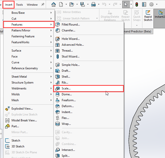
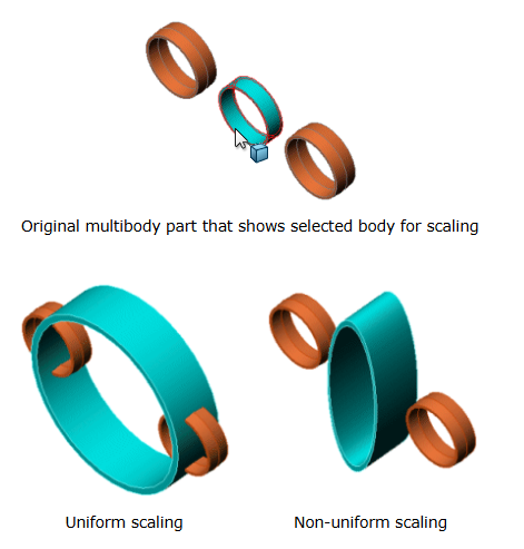
3. Select the scaling reference (Origin, Centroid, or Coordinate System), and apply a scale factor (uniform or non-uniform).

4. Save and rebuild the assembly

For faster results, especially in conceptual stages, you can convert the assembly into a part file.
Steps:

2. Next, open the saved part file and go to Insert > Features > Scale. Within the SOLIDWORKS Part file Scale feature, you can choose to scale selected bodies or the entire model.

3. Apply the Scale then save the part file.
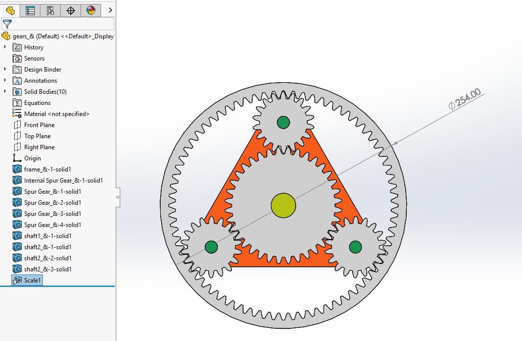
Scaling changes geometry but does not adjust dimensions, equations, or design logic. For production models, modifying dimensions is often a better approach.
Scaling can be applied relative to:
Choosing the correct reference ensures consistent positioning.
Use non-uniform scaling cautiously, especially for functional components.
Conclusion
Although SOLIDWORKS does not allow direct assembly scaling, engineers can achieve accurate results using structured methods. By scaling individual parts or leveraging conversion techniques, you can adapt designs effectively while maintaining control over your model.
Need Support?
If you require assistance with SOLIDWORKS or advanced simulation workflows, the SEACAD Technologies team is here to help you optimize your engineering processes. Please contact us via email at support@seacadtech.com, call our hotline at +65 6226 3784 or reach us on WhatsApp
Author: Jeff Wong, Engineer
References
SOLIDWORKS. (2012). Scale feature overview.
Javelin Technologies. (2020). How to scale an assembly in SOLIDWORKS.