

Waterjet, Plasma and Laser Machining in SOLIDWORKS CAM
The SOLIDWORKS CAM Technology Database can be customized to support the use of waterjet, Plasma and laser cutting machines.
Stock
The first consideration is to ensure that the stock size is larger than the part you are machining. Typically, you will cut around the outside shape of the part after you have cut all internal profiles. You do not need to add stock in the Z direction. The program will automatically detect the height and cut through based upon power or setting for the material specifications in the post processor.
SOLIDWORKS CAM provides the ability to select from different material types. These materials properties can be customized and utilized in the machining operations.
Tools
Specialized tools for the type of machining operation can be added to the Technology Database.
Typically, you would define a tool and set the tool diameter and comments that you would like to see in the post processor. Additionally, you would set the speeds and feeds for the material, the leadin/leadout desired to maintain a quality cut and the coolant setting.
Case Study: Plasma Workflow
In this case study, you will follow a typical workflow for machining with a plasma, waterjet or laser machine.
- First, Add flat end mill, in Tech DB.
Goto, TechDB è Mill Tool è Flat End Mill. Copy a Flat end mill change parameter as below:
Tool ID: 1MM Plasma DIA
Diameter(D1): 1mm
Comment: 1mm Plasma DIA
Stock and material group name: add è Low carbon alloy steel. Feed Rate settings:
XY Feedrate:700
Z federate: 700
Leadin feedrate: 400
Leadout feedtate: 400
Coolant type: Off

2. Open part and add tool to tool crib.

3. Create Mill part setup and Create pocket for inside features.
Select Mill setup 1, Right-click and select 2.5 Axis feature select Type Pocket.
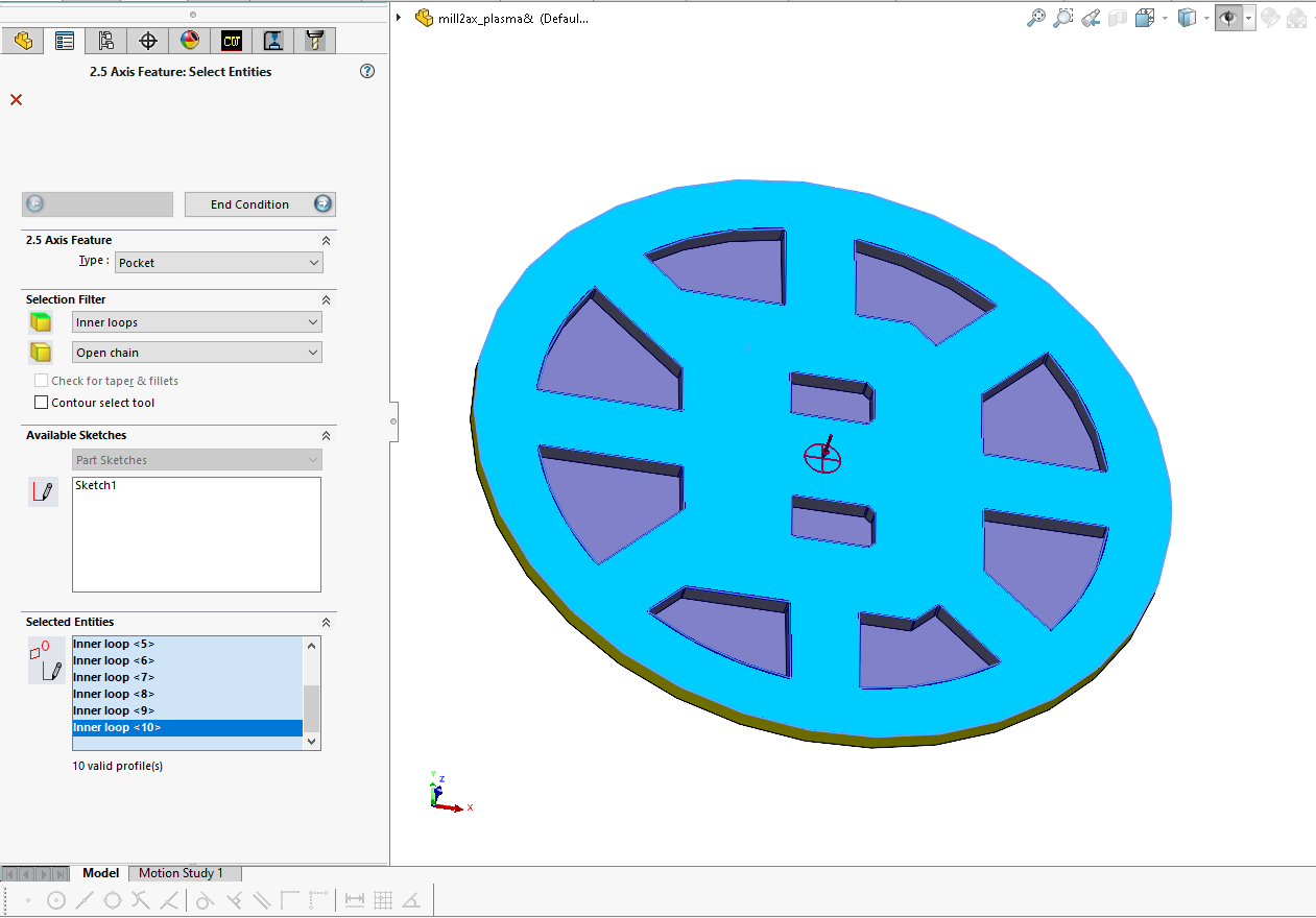
Set Face Selection filter to inner loops and select the top face of the part.
Click End Condition set to Upto stock.
Set strategy to finish.
Click OK.
4. Create a boss for outer profile.
Select Mill part setup 1, Right-click and select 2.5 Axis Feature.
Select Type, Boss.
Select the outer edge of the part.
Click End Condition set to upto Stock.
Click OK.
The Circular Boss feature is created.
5. Generate operation plans.
Click Generate operation Plan
6. Generate toolpath.
7. Modify operation parameters.
8. Simulate Toolpath.
9. Post process
Optionally you can post process the part using the Plasma Tutorial post processor.
10. Send NC program to the machine.
- For all Technical Support related queries please send an email to support@seacadtech.com or contact us at +65 6226 3784
- To know more about our products, email us at marketing@seacadtech.com or contact us at +65 6372 1416
- Learn more about our training programmes and courses here